Romi Design
Required Hardware
Additional items needed for Romi include AA batteries and a USB-Mini-B cable.
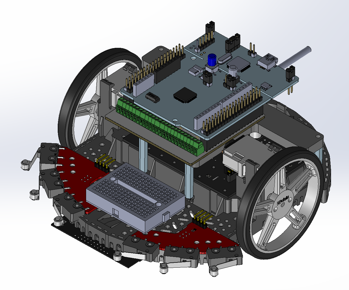
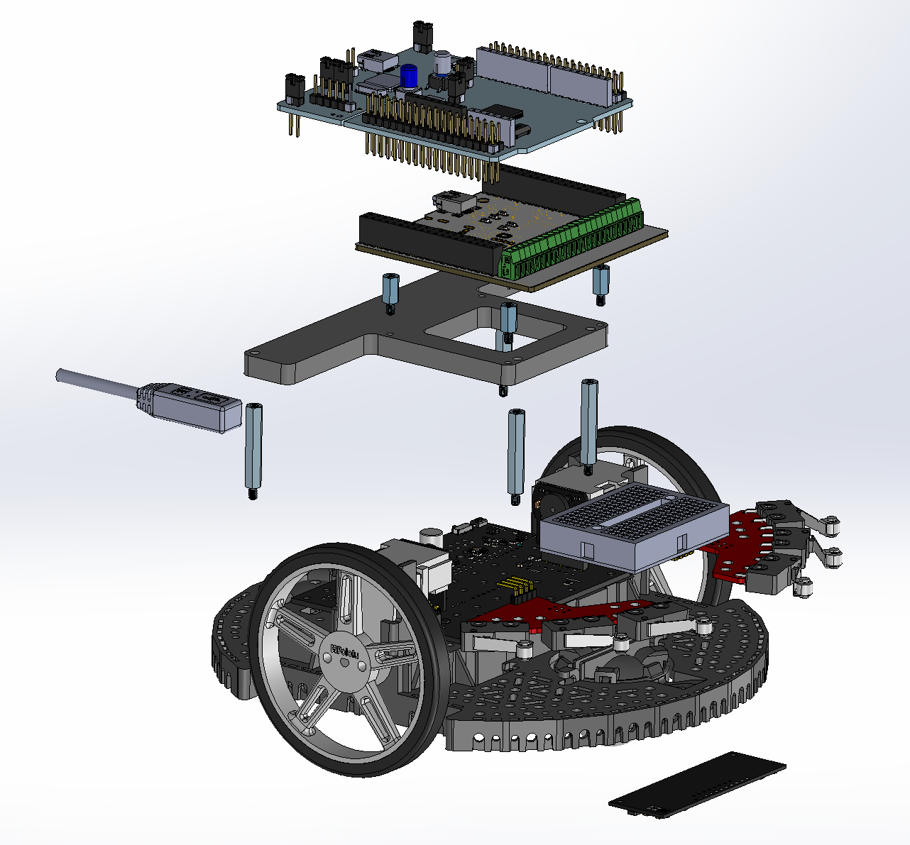
Mechanical Design
The Romi assembly is compact and designed for easy access to essential ports and hardware for maintenance. The NUCLEO is mounted above the Shoe of Brian and the power distribution board using stand-offs and an acrylic plate, providing ample space for mounting various sensors and routing the wiring harness.
The bump sensors are positioned at the front of the chassis to detect head-on collisions, as Romi is primarily intended to move forward. Both the IMU and IR sensor are mounted on the undertray of the chassis. However, it was crucial to position the IR sensor at the midpoint between the two wheels to accurately determine the centroid position, as it serves as the central sensor in the array. Additionally, a breadboard is placed at the front, allowing for easy connection of peripherals to the common 3.3V pin on the NUCLEO.
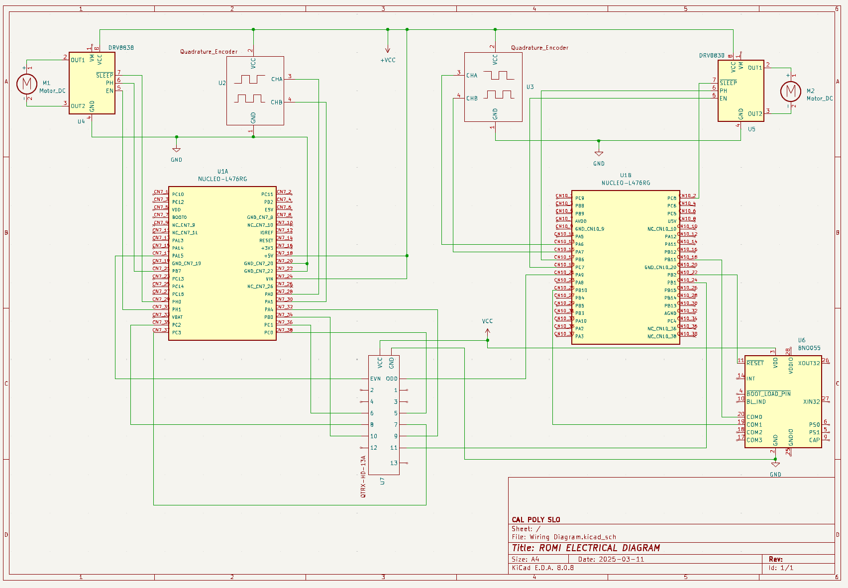
Electrical Design
Pin assignments on the NUCLEO that interfaced with hardware were selected based on the component or sensor requirements. For instance, the BNO055 IMU utilizes I2C communication for integration, addressing, and flexibility, while the IR sensor reads ADC pins to ensure proper calibration, performance, and processing. Additionally, motors and encoders were configured to use the least amount of timers possible.
Note: The HC-05 Bluetooth module was intended to utilize UART communication, but ended up out of scope for our project.